The service box includes a circuit breaker which can be used to shut off all the power in the house, or a switch with a handle located on the outside, and the service fuses inside. The cover on the service box is often sealed by the utility. Air conditioners are required to have a Service Shut Off on exterior of house.
The service box may stand alone, although in modern homes, the service breaker is often incorporated into the service panel. In either case, it is important that the rating on the box itself, is at least as large as the service entrance cables and fuses or breakers inside. For example, if a house has service entrance wire and fuses rated for 100-amps, a box rated for only 60-amps is not acceptable. More than 60- amps flowing through this box may lead to overheating.
Every home should have a disconnect means so the system can be shut off. Working on a live electrical system is very dangerous. In the U.S. (and in some Canadian situations) it is permitted on existing installations to have up to six switches to disconnect all the house power.
Electrical Codes
Wiring safety codes are intended to protect people and property from electrical shock and fire hazards. Regulations may be established by city, county, provincial/state or national legislation, usually by adopting a model code (with or without local amendments) produced by a technical standards-setting organisation, or by a national standard electrical code.
Electrical Service Box
The First Electrical codes were created in the 1880’s with the commercial introduction of electrical power. Many conflicting standards existed for the selection of wire sizes and other design rules for electrical installations.
The first electrical codes in the United States originated in New York in 1881 to regulate installations of electric lighting. Since 1897 the US National Fire Protection Association, a private non-profit association formed by insurance companies, has published the National Electrical Code (NEC). States, counties or cities often include the NEC in their local building codes by reference along with local differences. The NEC is modified every three years. It is a consensus code considering suggestions from interested parties. The proposals are studied by committees of engineers, tradesmen, manufacturer representatives, fire fighters and other invitees. Many of the NFPA codes have been adopted worldwide as the Standard for various types of equipment and installations. Sprinkers, Fire Hydrants, Fire Extinguishers, Airport Safety Reguations and Commercial Cooking Equipment to name just a few. In Canada the authority to use the NFPA publications typically comes from Canadian Standards such as the National Building Code of Fire Code.
Since 1927, the Canadian Standards Association (CSA) has produced the Canadian Safety Standard for Electrical Installations, which is the basis for provincial electrical codes. The CSA also produces the Canadian Electrical Code, the 2006 edition of which references IEC 60364 (Electrical Installations for Buildings) and states that the code addresses the fundamental principles of electrical protection in Section 131. The Canadian code reprints Chapter 13 of IEC 60364, but there are no numerical criteria listed in that chapter to assess the adequacy of any electrical installation.
Although the US and Canadian national standards deal with the same physical phenomena and broadly similar objectives, they differ occasionally in technical detail. As part of the North American Free Trade Agreement(NAFTA) program, US and Canadian standards are slowly converging toward each other, in a process known as harmonization.
To enable wires to be easily and safely identified, all common wiring safety codes mandate a colour scheme for the insulation on power conductors. In a typical electrical code, some colour-coding is mandatory, while some may be optional.
Service Boxes and Panels
In a conventional 60-amp service with circuit breakers, the breakers will trip when the current in either leg reaches 60-amps. Where fuses are used in the main service box, each fuse works independently. If more than 60-amps flows through one fuse it will blow. This leaves roughly half the house without power, including part of the electric stove, for example. If more than 60-amps flows through the other fuse, it too will blow, leaving the entire house without power.
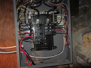
Federal Pioneer & Federal Pacific Electrical Panels
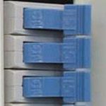
Federal Pioneer Panel Problems – The Electrical Safety Authority has revised and re-issued a Safety Flash that was originally published in 1997 – their concern is that potential problems might still exist for Federal Pioneer breakers that may not trip! Schneider Canada has announced a voluntary Replacement Program on certain NC015 and NC015CP Breakers. The affected circuit breakers are Federal Pioneer NC015 and NC015CP, Single Pole Rated 15A, Stab-Lok Circuit Breakers – Manufactured between August 1, 1996 and June 11, 1997. These circuit breakers can be identified by a Square / rectangular shaped BLUE colored handle Replacement breakers are identified by a hole drilled in the handle (Blue color) OR Replacement breakers manufactured after January 1, 1999 are identified with a rounded and ribbed handle (Blue color) Check for a square / rectangular handle with a hole, as illustrated or a rounded / ribbed handle – these are OK and not impacted by the recall notice. Breakers with black handles are also OK to use and not impacted by the recall notice. Contractors/Electricians: For any suspect blue-handled circuit breaker replace the breaker and return it to Schneider Electric for full credit, or contact Schneider Electric Customer Care Centre at 1-800-565-6699 or the Schneider Electric Recovery Administration team, at 1-866-333-1490 for additional information. Customers should call their contractor or call Schneider.
(1) Except as permitted by Sentence (6), smoke alarms conforming to CAN/ULC-S531, “Smoke Alarms”, shall be installed in each dwelling unit and, except for care, care and treatment or detention occupancies required to have a fire alarm system, in each sleeping room not within a dwelling unit.
(2) At least one smoke alarm shall be installed on each storey and mezzanine of a dwelling unit.
(3) On any storey of a dwelling unit containing sleeping rooms, a smoke alarm shall be installed in,
(a) each sleeping room, and
(b) a location between the sleeping rooms and the remainder of the storey, and if the sleeping rooms are served by a hallway, the smoke alarm shall be located in the hallway.
(4) A smoke alarm shall be installed on or near the ceiling.
(5) Except as permitted by Sentence (6), smoke alarms required by Sentence (1) shall,
(a) be installed with permanent connections to an electrical circuit,
(b) have no disconnect switch between the over current device and the smoke alarm, and
(c) in case the regular power supply to the smoke alarm is interrupted, be provided with a battery as an alternative power source that can continue to provide power to the smoke alarm for a period of not less than seven days in the normal condition, followed by 4 min of alarm.
(6) Suites of residential occupancy are permitted to be equipped with smoke detectors in lieu of smoke alarms, provided the smoke detectors,
(a) are capable of independently sounding audible signals within the individual suites,
(b) except as provided by Sentence (7), are installed in conformance with CAN/ULC-S524, “Installation of Fire Alarm Systems”, and verified in conformance with CAN/ULC-S537, “Verification of Fire Alarm Systems”, and
(c) form part of the fire alarm system.
(7) Smoke detectors permitted to be installed in lieu of smoke alarms as provided in Sentence (6) are not required under Clause (6)(b) to sound an alarm throughout the rest of the building, provided they sound localized alarms within individual suites and otherwise meet the requirements of Clause (6)(b).
(8) If more than one smoke alarm is required in a dwelling unit, the smoke alarms shall be wired so that the actuation of one smoke alarm will cause all smoke alarms within the dwelling unit to sound.
(9) A smoke alarm required by Sentence (1) shall be installed in conformance with CAN/ULC-S553, “Installation of Smoke Alarms”.
(10) Except as permitted by Sentence (11), a manually operated silencing device shall be incorporated within the circuitry of a smoke alarm installed in a dwelling unit so that it will silence the signal emitted by the smoke alarm for a period of not more than 10 min, after which the smoke alarm will reset and again sound the alarm if the level of smoke in the vicinity is sufficient to reactuate the smoke alarm.
(11) Suites of residential occupancy equipped with smoke detectors installed in conformance with CAN/ULC-S524, “Installation of Fire Alarm Systems”, as part of the fire alarm system in lieu of smoke alarms as permitted by Sentence (6), need not incorporate the manually operated silencing device required by Sentence (10).
(12) The sound patterns of smoke alarms shall,
(a) meet the temporal patterns of alarm signals, or
(b) be a combination of temporal pattern and voice relay.
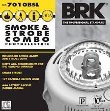
(13) Smoke alarms required by Sentence (1) shall have a visual signalling component conforming to the requirements in 18.5.3. (Light, Color and Pulse Characteristics) of NFPA 72, “National Fire Alarm and Signaling Code”.
(14) The visual signalling component required by Sentence (13) need not,
(a) be integrated with the smoke alarm provided it is interconnected to it,
(b) be on battery backup, or
(c) have synchronized flash rates, when installed in a dwelling unit.
(15) The luminous intensity for visual signalling components required by Sentence (13) that are installed in sleeping rooms shall be a minimum of 175 cd.
Types of Smoke Alarms
There are many types of smoke alarms, each with different features. Alarms can be electrically connected, battery-powered or a combination of both. The combination with a hush feature to reduce nuisance alarms are highly recommended. Smoke alarms commonly use one of two types of technology to detect the presence of smoke in the air:
These alarms consist of a light emitting diode and a light sensitive sensor in the sensing chamber. The presence of suspended products of combustion in the chamber scatters the light beam. This scattered light is detected and sets off the alarm. Photoelectric models are best suited for living rooms, bedrooms and kitchens. This is because these rooms often contain large pieces of furniture, such as sofas, chairs and mattresses which will burn slowly and create more smoldering smoke than flames.
An ionization smoke alarm uses a small amount of radioactive material to ionize air in the sensing chamber. As a result, the air chamber becomes conductive permitting current to flow between two charged electrodes. When products of combustion enter the chamber, the conductivity of the chamber air decreases. When this reduction in conductivity is reduced to a predetermined level, the alarm is set off. This is the most common type of smoke alarm. Ionization models are best suited for rooms that contain highly combustible materials that can create flaming fires. These types of materials include flammable liquids, newspapers and paint related products. We recommend installing this type of smoke alarm in the kitchen where grease fires can occur.
Every manufacturer has these alarms. They can be powered by a 9-volt battery or 3-4 double A batteries or a 10-year sealed lithium battery. In rental units, it’s imperative that the landlord install and provide batteries for these alarms.
These devices use a radio frequency to cause the other alarms to sound when one is activated. This can provide a higher level of security to homes that do not have hardwired alarms.
These devices are wired into the electrical system of the home. In homes built after 1986, only the alarm in the upper level by the sleeping area needed to be hardwired, the other levels could have battery operated devices. These alarms should have battery back up as power outages can render you unprotected if there isn’t one. This is the time when higher hazards exist when people use alternate methods of light and heating. Hardwired alarms also need to be changed after 10 years. These cannot be replaced with battery-operated alarms as this would cause a decreased level of protection and would be a fire code violation.
Homes built with interconnected hardwired alarms are protected with constant notification on all levels. When replacing these alarms make sure that the alarms purchased are compatible with the others in the house. If not they will not signal correctly and reduces level of protection.
Some manufactures have created smoke alarms that have dual sensing systems in them to assist with nuisance alarms. It would require both the smoke sensing device and the fire gas sensing device to activate before an alarm is triggered. These are helpful in homes where the style of cooking creates more smoke that average or where there have been problems with nuisance alarms that cannot be solved by the hush button feature.
SMOKE DETECTORS
A smoke detector is a device that senses smoke, typically as an indicator of fire. Commercial security devices issue a signal to a fire alarm control panel as part of a fire alarm system, while household smoke detectors, also known as smoke alarms, generally issue a local audible or visual alarm from the detector itself.
Smoke detectors are housed in plastic enclosures, typically shaped like a disk about 150 millimeters (6 in) in diameter and 25 millimeters (1 in) thick, but shape and size vary. Smoke can be detected either optically (photoelectric) or by physical process (ionization), detectors may use either, or both, methods. Sensitive alarms can be used to detect, and thus deter, smoking in areas where it is banned. Smoke detectors in large commercial, industrial, and residential buildings are usually powered by a central fire alarm system, which is powered by the building power with a battery backup. Domestic smoke detectors range from individual battery-powered units, to several interlinked mains-powered units with battery backup; if any unit detects smoke, all trigger even in the absence of electricity.
Function Smoke detectors protect people by notifying them of fire in the home, especially when people are sleeping. They usually provide an audible alarm, and some have a visual alarm consisting of a flashing light.
Ionization Type Detectors
An ionization smoke detector uses a radioisotope, typically americium-241, to ionize air; a difference due to smoke is detected and an alarm is generated. Ionization detectors are more sensitive to the flaming stage of fires than optical detectors, while optical detectors are more sensitive to fires in the early smoldering stage.
The smoke detector has two ionization chambers, one open to the air, and a reference chamber which does not allow the entry of particles. The radioactive source emits alpha particles into both chambers, which ionizes some air molecules. There is a potential difference (voltage) between pairs of electrodes in the chambers; the electrical charge on the ions allows anelectric current to flow. The currents in both chambers should be the same as they are equally affected by air pressure, temperature, and the ageing of the source. If any smoke particles enter the open chamber, some of the ions will attach to the particles and not be available to carry the current in that chamber. An electronic circuit detects that a current difference has developed between the open and sealed chambers, and sounds the alarm.[15] The circuitry also monitors the battery used to supply or back up power, and sounds an intermittent warning when it nears exhaustion. A user-operated test button simulates an imbalance between the ionization chambers, and sounds the alarm if and only if power supply, electronics, and alarm device are functional. The current draw of an ionization smoke detector is low enough for a small battery used as sole or backup power supply to be able to provide power for months or years without the need for external wiring.
Carbon Dioxide Detectors
Carbon monoxide sensors detect potentially fatal concentrations of carbon monoxide gas, which may build up due to faulty ventilation where there are combustion appliances such as heaters and cookers, although there is no uncontrolled fire outwith the appliance.
High levels of carbon dioxide (CO2) may indicate a fire, and can be detected by a carbon dioxide sensor. Such sensors are often used to measure levels of CO2 which may be undesirable but not indicative of a fire; this type of sensor can also be used to detect and warn of the much higher levels generated by a fire. One manufacturer says that detectors based on CO2 levels are the fastest fire indicators, and also, unlike ionization and optical detectors, detect fires that do not generate smoke, such as those fueled by alcohol or gasoline. CO2 fire detectors are not susceptible to false alarms due to particles, making them particularly suitable for use in dusty and dirty environments.
Photoelectric Detectors Photoelectric detectors have a small light source that normally misses a sensor that is set up out of the target area. Smoke particles deflect the light onto the sensor, creating an alarm. Photoelectric detectors are good at sensing smoky fires.
Not Heat Detectors Smoke detectors are not heat detectors. High temperatures will not trigger smoke detectors.
Power Source Smoke detectors require an electric power source from a battery, house voltage, or both. Batteries may be conventional alkaline type that last one to two years, or lithium type that can last 10 years. Battery powered detectors typically have a power indicator light that is permanently on or flashes intermittently. Most units emit a loud chirping sound every few seconds when the battery is low.
120 Volt Systems Many authorities insist on smoke detectors powered by the house electrical system. These detectors don’t need batteries changed and can be connected to any junction box, like a light fixture. Smoke detectors are not usually on a dedicated circuit, but detectors should never be on a switched part of a circuit, so that they don’t get turned off accidentally.
Battery Backup Some detectors operate on house power but have battery backup systems. The thinking is that a fire, especially if it’s electrical, may cut power to the detector before it can sound an alarm.
Interconnected Detectors Many jurisdictions call for smoke detectors to be interconnected, so if one senses smoke, all will sound an alarm. This desirable arrangement is typically only found on newer homes. The interconnection most often uses conventional 120 volt house wiring (typically with 14 gauge, 3-conductor wire), but some are on a low voltage system.
Location Smoke detector location is a somewhat controversial issue. Everyone agrees there should be at least one detector in each home. There is also agreement that the detector should be near the sleeping area. Some say there should be a detector on every level of the home with sleeping quarters. Others say there should be a detector on every floor level, regardless.
Detectors In Bedrooms? Some say there should also be detectors in bedrooms, rather than just in the hall ways. This protects people sleeping from a fire that starts in the bedroom. This is particularly helpful if the door is closed, because a detector in the hall may not sound quickly enough to save the person in the bedroom. One other recommendation is to ensure the detectors near sleeping areas are between the escape path and the bedrooms (not at the other end of the hall).
Humidity Can Cause False Alarms Smoke detectors should not be in or adjacent to kitchens or bathrooms, since high humidity levels can cause false alarms.
Not In Corners Smoke detectors should be installed on the ceiling because smoke rises. While some say on or near the ceiling, we prefer the detector to be away from wall /ceiling intersections, where dead air may delay activation. We prefer the detector to be near the middle of the room or hall width to help ensure early warning.
Testing Smoke Detectors
Test your smoke alarms regularly by pressing the test button or by using smoke from a smoldering incense stick.
Replace batteries regularly. Install a new battery in each alarm at least once a year. All battery-operated smoke alarms are required to emit a warning sound, usually an intermittent “chirp” when the battery power is low. When warning chirp sounds, replace your battery immediately. Never wait. Change your batteries when you change your clocks in the spring and fall. Smoke alarms do wear out, so if you think your alarms are more than 10 years old, replace them with new ones. Newer smoke detectors start aan automatic dating mechanism as soon as activated. Annoying chirping will start in 10 years so ensure you replace your parents or grandparents smoke detectors parior to the end of 10 year period to prevent getting a panic call in middle of night 🙂
Central Station Alarms Some smoke detectors are connected to central station alarm monitoring facilities. These central stations will respond to an alarm, typically by phoning the home and then sending the fire department, if they don’t get an immediate response from the occupants. This kind of alarm connection typically has the detectors in the home interconnected. These monitored detectors are commonly found in homes with security systems.
Replacing Smoke Alarms
When you replace your smoke alarm you have to maintain the level of protection that was required at time your home was built. If your smoke detectors are all inter-connected you have to maintain that standard of protection. It is recommended that you take your old smoke alarm with you to ensure you buy the proper model. For example you cannot replace a interconnected smoke alarm with a battery operated smoke alarm from Costco.
Hiring a WETT Certified Inspector
Most insurance companies now require a WETT Certified Inspection on any wood burning appliances prior to issuing a Home Insurance policy. When you buy a new home or change insuarance companies be prepared to provide them with an Inspection Report from a WETT Certified Inspector.
WETT Inspection Barrie is available 7 days a week for your convenience. Call Roger today 705-795-8255
Since the introduction of electricity in homes, circa. 1910, various electrical wiring methods have been used. The main types can be grouped into five separate categories. All wiring types if installed and maintained correctly can be safe and conforming to electrical standards. However, if not installed or maintained correctly, each has potential risks.
1910–1950: “Knob and tube”
Knob and tube (K&T) wiring was installed in virtually all houses from 1920 to 1950. It incorporated single conductors run along the sides of the wooden framing. The conductors were supported by ceramic knobs and insulated from contact with wooden joists by ceramic tubes. Electrical splices (wire to wire connections) were done in free air, soldered and covered with insulating tape. The conductors were covered in flame-retardant cloth impregnated with rubber. The conductor quality was excellent, consisting of heavy gauge copper wire with a minimal number of soldered connections enroute to receptacles and lights. However there was no ground conductor. Thus the receptacles of knob-and-tube circuits were not grounded.
Risk in modern homes:
The safety concerns of knob-and-tube wiring are due to alterations or modifications of the original wiring.
UNGROUNDED RECEPTACLES: Original 2-prong ungrounded receptacles have often been exchanged for modern 3-prong receptacles, giving false impression of ground protection.
POOR CONNECTIONS: To meet the house electrical requirements, circuits are often found tapped to the knob-and-tube, likely done by the homeowner or persons not qualified as residential electricians. These add-on circuits can be most dangerous, resulting in hot-spots at the added connections.
INSULATION BREAKDOWN: If there has been “overfusing” (overrated fuses or breakers installed on the circuits) there can be insulation breakdown, as overfusing combined with overloading the circuits significantly raises the temperature of the conductors beyond their designed temperature limits, resulting in a fire hazard.
Inspection procedure:
An ESA inspection or a Master Electrician will check all of these above concerns to determine if the wiring is acceptable. Receptacles are inspected to assure that they are the correct type. The quality of the connections is determined by “voltage-drop testing” (an accurate method to determine if there are any poor connections enroute to the receptacles). The panels are checked for any signs of overfusing and the insulation is checked. If any of the above are found to be deficient, the knob-and-tube circuit is not acceptable and repairs are identified.
1950–1962: Ungrounded twin-conductor cable, NMD 1
Twin-conductor cable replaced knob-and tube in early 1950s due to ease of installation. Contained two insulated conductors wrapped in paper and black tar-based cloth casing. Originally contained no ground wire (NMD1), thus the receptacles were not grounded. The insulation temperature rating of this cable was 60°C. Grounded receptacles were not required until 1962.
Risk in modern homes:
As with knob-&-tube circuits, original 2-prong ungrounded receptacles have often been exchanged for modern 3-prong receptacles, giving false impression of ground protection. This is an easy check and an easy repair. Ground-fault circuit interruption (GFCI) receptacles or breakers can be installed, providing 3-prong receptacles with ground protection. Most insurance companies will not insure a home with Knob and Tube wiring.
Ground conductors were required in residential cables in 1962. NMD 3 was introduced containing a ground conductor. Homes were now wired with modern, 3-prong outlets. As with NMD1, NMD3 had an insulation temperature rating of 60°C. Later NMD6 was introduced with an increased temperature rating of 75°C.
Risk in modern homes:
Many modern fixtures generate considerable heat inside the enclosure, particularly recessed lighting fixtures (pot light). A number of fires have been reported in these fixtures as a result of cables with low temperature rating. Since 1984 the electrical code requires that all ceiling fixtures be wired with a cable rated at 90°C. Cables rated at 60°C and 75°C are not suitable for modern fixtures. The house should be checked to confirm that these older cables are not used for modern lighting.
1965–1974: Aluminum branch circuit wiring.
Installed in the vast majority of homes during this period. Provided an inexpensive solution to escalated price of copper at that time.
Risk in Aluminum Wiring Connections:
Loose connections where aluminum meets copper have shown to develop over time. This results in very hazardous conditions, which often lead to fire. US Consumer Product Safety Commission reports that aluminum-wired homes are 55 times more likely to have one or more connections reach “Fire Hazard Conditions” than homes wired with copper only. The concern is not the cable, but the aluminum-copper connections. Many insurance companies will not insure homes with ESA. Some may require an ESA inspection prior to insuring property.
Inspection procedure:
The Electrical Safety Authority has received an increasing number of questions about the safety of aluminum wiring. In particular, purchasers or owners of homes built from the mid 1960’s until the late 1970’s with aluminum wiring are finding that many insurers will not provide or renew insurance coverage on such properties unless the wiring is inspected and repaired or replaced as necessary and this work is inspected by ESA and a copy of the certificate of inspection is provided to the insurer. In some cases the insurer may require replacement of the aluminum wiring with copper wiring. Check with your insurance company for their requirements.
1984–Present: Modern NMD90 cable
The primary cable used today for the wiring of homes is NMD90 (formerly NMD7). Modern NMD90 cable contains two conductors and a ground enclosed in a PVC jacket. It is an excellent all-round indoor cable suitable for modern lighting. It has an insulation temperature rating of 90°C.
Risk in using Wrong Types of Cables:
The cable is designed for home wiring in dry locations only. Not designed for outdoor, underground or wet locations. The home should be checked to confirm that it has not been installed in incorrect locations.
There are always Consumer Alerts for various products, fixtures or failures of items. Read our Consumer Alerts Page
There are many common electrical issues that I have found over and over again while performing home inspections in the past ten years. You might want to look around your own home and see if any of these issues are present.
These electrical issues are also Red Flags that work was most likely done without a permit, which in a basement renovation means the complete basement was finished without the proper building permit of subsequent inspections.
Electrical wiring in metal stud walls
When using metal stud walls the electrical cable requires approved inserts (grommets) to protect the cable where it passes through the metal stud. ESA also states in its bulletin that NMSC cable cannot be fished through a metal stud wall.
Mechanical Protection Required in Attic
A running board must be installed for NMSC installed in attic where distance between joist and rafter exceeds 1 M.
Kitchen Islands
If you install a fixed kitchen island with a work surface greater than 300 mm X 600 mm then an electrical outlet is required to be installed.
Cold Air Returns
While you are allowed to have electrical cables installed in a cold air return, the entry and exit point must have an approved insert to protect the cable. You are not allowed to “fish” and electrical cable through a cold air return.
Bundling of Electrical Cables
Electrical cables maybe bundled as long as approved cable ties rated for 23 kg or greater are used and bundled cables are not in contact for more than 600 mm.
TWO GFCI outlets on same circuit
Most builders will install a single GFCI outlet and use this to protect the installed outlets downstream. This is common for both exterior outlets and for bathrooms. Because most home owners do not have a GFCI tester they wrongly assume that because there are no test or reset buttons on the outlet it is not protected. Many times I have tested a GFCI protected outlet and then had to hunt down the extra one the homeowner has installed in order to get a reset. The circuit is still fully protected but it is not good workmanship to add GFCI outlets to a circuit that is already protected.
Lights in Showers
Lights in showers have to rated for use in damp location. This is typically a pot mounted light with a glass lens. Sometime individuals will remove glass lens to install a higher wattage bulb, this is not permitted and is an electrical shock hazard.
GFCI’s & Light switches in Bathrooms
Light switches in bathrooms have to be 1 metre away from shower or bathtub or GFCI protection is required. GFCI protection for outlets has been required since 1975.
Kitchen GFCI’s
Kitchen outlets were not required to have GFCI outlet protection until 2003.
Home owners who do their own electrical wiring should have it inspected by ESA or other Licensed Electrical Inspector prior to covering up wiring. Failure to do so could adversely affect the resale value of your home and even jeopardize your family’s safety.
If you have any questions about electrical problems or home inspection information please contact Roger Frost at Barrie Home Inspections.
The home owner is responsible to test their Ground Fault Circuit Interrupter Outlet every month, which I am sure we all do, Right? I know after a long day of testing other peoples outlets, I do not come home and test mine. Shocking…and it could be!
Electrical manufactures have developed a GFCI outlet that will test itself every 60 seconds. It will not only check the Ground Fault function but ensure unit is correctly wired. Improperly wired GFCI outlets are quite common and considering most incorrectly wired GFCI’s are found in the home bathroom the chances of disaster are enormous.
These GFCI’s will still have the manual test mode but the diagnostic testing will be on a continuous 60 second cycle and will immediately shut down the circuit if a “Ground Fault” is detected. There will also be a red flashing light indicating unit has lost capability to provide protection. If outlet has reversed wiring condition it will not be able to be manually reset.
When manually testing GFCI the unit is tested by circuit board at the same time to ensure functional capabilities.
Typical behaviour of a GFCI outlet will disconnect a circuit whenever it detects that the electric current is not balanced between the energized (line) conductor(s) and the return (neutral) conductor. In normal circumstances, these two wires are expected to carry matching currents, and any difference usually indicates a short circuit or other electrical anomaly is present. Even a small leakage current can mean a risk of harm or death due to electric shock if the leaking electric current passes through a human being; a current of around 30mA (0.030 Amps) is potentially sufficient to cause cardiac arrest or serious harm if it persists for more than a small fraction of a second.
Many home owners like to install electrical equipment and wiring. As a Professional Home Inspector I would like to list some of the common mistakes that I encounter when inspecting homes in the Barrie ON area. Note: Although a home owner is allowed to install his own electrical wiring, they are required to take out a permit and have installation inspected by the ESA.
Many home owners use metal stud walls in basements, which require special grommets or standoffs when installing electrical cables. Metal studs on basement exterior walls is not a good ideas as metal conducts heat and cold extremely well and can also cause moisture issues due to humidity in air contacting cold areas created by conduction of cold through metal studs.
Most custom builders will use the mould proof treated wood studs when framing in basements. Pressure treated lumber is recommended for sill plate with a moisture barrier between concrete and wood required by building code.
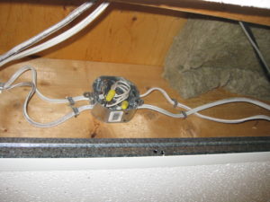
Junction Boxes
Ontario codes 12-3016(1) and 12-112(3) specify that all junction boxes must remain accessible. Junction boxes also require a cover plate to be installed.
Kitchen Installations
Kitchens require at least 2 15 amp multi-wire (split receptacles) or 20 Amp (T Slot receptacles) branch circuits to supply receptacles located along the kitchen counter work surface.
210.52(B)(1)
(1) Wall Counter top Spaces. A receptacle outlet shall be installed at each wall countertop space that is 300 mm (12 in.) or wider. Receptacle outlets shall be installed so that no point along the wall line is more than 600 mm (24 in.) measured horizontally from a receptacle outlet in
that space.
Exception: Receptacle outlets shall not be required on a wall directly behind a range, counter-mounted cooking unit, or sink in the installation described in Figure 210.52(C)(1).
This also includes the requirement for kitchen islands to have an outlet installed.
Ontario electrical code requires a dedicated electrical outlet to be located behind fridge location. This circuit is allowed to provide power to a clock also.
GFCI ( Ground Fault Circuit Interrupter)
Exterior receptacles within 8ft (2.5m) of finished grade (since 1975).
Bathroom & washroom receptacles (since 1986).
Receptacles within 5ft (1.5m) of all sinks (since 2006).
Hydro massage bathtubs must be GFCI protected.
Spas and hot tubs must be GFCI protected.
Receptacles, equipment, and buildings around pools have numerous requirements.
Metal Stud Wall Installation
The Ontario Electrical Safety Code requires that metal stud partitions be bonded to
ground so that the branch circuit over current device will operate in the event the studs become energized.
Securing Cable at Boxes
The electrical cable is required to be secured within 8” to 12” of box with a wire staple. Also you must have a 12” loop of unbroken cable on the outside of box or 6” of cable end available on the interior side of finished wall to permit replacement without major reconstruction.
Extension Cords
Flexible extension cords must never take the place of permanent wiring; they are not designed or intended for permanent installations. Once the task has been completed, the cord should always be disconnected and properly stored away for future use.
Protection of Electrical Cables
Electrical cable should be protected against mechanical damage where it passes through floors or on the surface of walls in exposed locations under 5 feet from the floor.
If burying an electrical cable you should call the ESA and find out the exact requirements for your particular location. The area where cable is buried determines depth and protection required
Dedicated Circuits These are some of the most common items that require a dedicated electrical circuit for:
Fridge Range or stove Cook top Water Heater Heat/Air Conditioning Dishwasher Clothes Washer Clothes Dryer Furnace Exterior lights and Outlets
Renovations without a Building Permit
The major concern when performing a home inspection and these deficiencies are noted is the fact that you now know that the work was done without a permit and that would most likely apply to all the work done by homeowner.


 detector on every level of the home with sleeping quarters. Others say there should be a detector on every floor level, regardless.