Electrical Information – Aluminum Wiring
Electrical Information – Barrie Home Inspection brings you an alert that concerns aluminum wiring installed in homes between 1965 and 1973. If you’re living in a house that 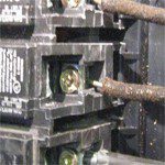 was built between the years 1965 to 1973, there’s a good chance your home is at increased risk for electrical fires if it has aluminum house wiring. During that period, about 1.5 million homes were wired with aluminum wiring because copper wire was too expensive. Unfortunately, this older aluminum house wiring proved to be a poor substitute for copper. Research conducted by the U.S. Consumer Product Safety Commission shows that homes wired with aluminum wire manufactured before 1972 are 55 times more likely to have one or more connections reach “Fire Hazard Conditions” than a home wired with copper. After 1973, copper once again become the predominant wire used in new house construction, renovations and rewiring.
Making Aluminum Wiring Safe
For those homes that have aluminum wiring, a few simple steps can help prevent some of the potential hazards. The Leviton Institute recommends that homeowners consider calling in a qualified electrician to inspect all the switches and receptacles in their homes and, if necessary, replace them with devices made specifically for aluminum wiring. These devices carry the designation of CO/ALR, which stands for copper/aluminum.
Underwriters Laboratory lists CO/ALR devices primarily for use with aluminum wire because they use special metals at the terminal areas that are compatible with aluminum wire.
Identifying Aluminum Wiring
Removing the main electrical panel cover is the best way of determining if there is any aluminum wiring installed. Personally I always look at the neutral bar connections to find any aluminum wire. If the are a junction boxes close to the main panel I will always remove the cover and wire nuts to ensure copper wire cable has not been attached to make panel connections. Aluminum wiring has “Al” or “Aluminum” marked every few feet along the length of its insulating jacket. CO/ALR wiring devices, like the one shown above, have special terminals designed just for aluminum wiring.
Also watch for the warning signs that typically precede a serious electrical problem. These signs include faceplates on outlets or switches that are warm to the touch, lights that flicker on and off, circuits that no longer work, and the smell of burning plastic at outlets or switches. Because of the potential dangers posed by aluminum wiring, the Leviton Institute advises homeowners not to open, disassemble or touch any electrical panels, devices, or components if you are not familiar with aluminum wiring.
Other areas in the house that should be inspected include lighting fixtures, such as chandeliers and outdoor porch lights, and appliances that are wired directly to a branch circuit, such as an air-conditioning unit.
If you suspect that your home has aluminum wiring, have a qualified electrician conduct a thorough home inspection. Even room additions or circuits rewired or added between 1965 and 1973 may contain aluminum wiring.
Electrical Information – Aluminum Wiring
Electrical Information concerning Aluminum Wiring – In the late 1960’s and early 1970’s copper prices rose and contractors/electricians switched from copper to lower costing aluminum wiring. Although no longer common for distribution circuits, aluminum wiring is still used today in certain applications. For example, 240 volt circuits for stoves and dryers. It sometimes is used on the main service entrance wire from the road to the house. In Barrie Ontario, for example, there are complete sub-divisions that have been wired completely with aluminum wiring. Napoleon Home Inspections, in the course of a normal inspection, will remove the main cover panel to ensure that any aluminum wire is identified. Some home owners go to great lengths to disguise their aluminum wiring, using junction boxes to switch from copper to aluminum and by pushing the wire completely up to the insulation covering to hide the fact that it is aluminum. These tricks will fool the casual inspection but will not stand up to the inspection standards of a Certified Home Inspector.
Concerns with this type of wiring have arisen, for example, when aluminum wire is connected to devices (eg. receptacles, light fixtures) which were not designed for aluminum, or, when aluminum and copper wires are attached. In these cases a reaction can occur causing the connections to fail, perhaps become disconnected, and/or, potentially overheat, spark and catch fire. Symptoms of this can sometimes be seen in the dis-colouration of receptacles, flickering lights, or the smell of hot plastic insulation.
The conductivity of aluminum is not as good as copper so a different, thicker, gauge wire must used. For example, today the most common copper wire size is 14 gauge. The comparable aluminum wire size used is 12 gauge.
Ontario Hydro – Aluminum Wire
In their most recent 1997 Safety Notice, Ontario Hydro states: “Aluminum wiring in residential installations will operate as safely as any other type of wiring if the proper materials are used and it is installed as per the manufacturer’s instructions and the Ontario Hydro Electrical Safety Code.”
Special care must be taken to ensure, for example, that connections are made to receptacles that are suitable for aluminum wiring. Further, where aluminum and copper wires are connected that proper paste/flux, and/or, the appropriate wire connectors, are used.
Regardless of the wiring type used, no circuits should overloaded or over fused.
What do you do if you suspect a problem? Have a qualified electrician check:
1) Terminations at devices without removing or disturbing them.
2) Cut back any damaged aluminum conductors and join these to a copper tail using a connector approved for use with aluminum. These connectors are coloured either brown or purple, depending on the manufacturer. The copper tail is then terminated at the terminal screws of an ordinary device (which includes approved receptacles, etc.). Or, cut back any damaged aluminum conductors and re-terminate at a new device bearing the appropriate marking. Only devices bearing the mark CO/ALR are currently approved for use with aluminum wiring.
3) Panel board terminations for signs of overheating.
4) Fuses present for heavy loads are temperature sensitive type (D or P).
Items Inspected – detailed description of what items are inspected and some common deficiencies found during those inspections.
Electrical Information – State Farm Insurance
State Farm Insurance – Primarily in the 1960s and 1970s, many electrical contractors used aluminum wiring instead of copper wiring as a way to save money and lower construction costs. However, a number of electrical fires have been attributed to aluminum wiring. Many building codes have been rewritten to not allow the use of aluminum wire for branch circuit wiring in houses.
Copper vs. Aluminum — The Test Results are in!
Tests have demonstrated aluminum wiring has inherent properties that make it more susceptible to fires when it was not installed correctly. Here are some of the problems with using aluminum wiring to conduct electricity.
- Aluminum does not conduct electricity as well as copper. An aluminum wire generates more heat.
- Aluminum is more brittle than copper. Wire is more likely to break or crimp if it is brittle. Arcing can occur if a wire breaks or crimps. This can cause very high temperatures inside the wall or ceiling
- Aluminum is more likely to corrode than copper.
- Aluminum will oxidize if it comes in contact with moisture. This oxidation removes the pure aluminum and makes the wire thinner. A thinner wire creates more heat when electrical current is running through it.
- Oxidation also causes the wire to expand, puts pressure on the protective plastic coating on the wire, and can cause the plastic to split. If any of these occur, arcing may result which can cause fires.
- Aluminum expands and contracts more than copper. This puts additional stress at all connections such as outlets and switches. If these become loose, arcing can occur at these points.
If contemplating buying an older home with aluminum wiring or updating a home with aluminum wiring, contact a certified electrician to gain their expertise and opinion regarding the dangers of aluminum wiring. State Farm® believes the information contained in the Good Neighbor House® is reliable and accurate. We cannot, however, guarantee the performance of all items demonstrated or described in all situations. Always consult an experienced contractor or other expert to determine the best application of these ideas or products in your home. State Farm has since updated their Web Page….Visit State Farm
Electrical Information – Don’t Be Shocked
Power failures are usually common place in rural areas, and can also be neighborhood or even regional events. But problems of electrical safety and capacity also surface in household wiring, particularly if the house is more than 20 years old. In older residential homes that don’t measure up, the most common problems, identified by the Copper Development Association, was worn wiring, not enough circuits and overloading by using extension cords. There are more obvious trouble spots that a licensed electrician might have to tackle to make your home safe.
One such problem area is High attic temperatures. To permit a free-flowing supply of electricity, wiring has to be large enough to carry the load. If it isn’t, the power, in a way, is forced through the wire, which offers more resistance. That resistance, in turn, produces heat, which can lead to serious problems, including fires.
Problems can and do occur in attics, where even wiring that’s adequate for the load can overheat because the space is so hot in the summer. Overheating also can be a problem if attic wires are bundled together, for instance, to pass through holes in framing. But the best safeguard against overheating in attic wiring is to use wires with larger diameters that offer less resistance. For example, if the circuit calls for 14-gauge, use 12-gauge. According to the American Wire Gauge system, the lower the number, the larger the wire diameter and capacity.
Aluminum wiring connections. Because of the shortage and rising cost of copper in the 1960s and 1970s, many homes were wired with aluminum. The Consumer Product Safety Commission estimates that 2 million homes were built with this alternative between 1965 and 1974. Aluminum wiring of that era was more brittle than copper, more likely to break during handling and more likely to corrode. In contact with moisture, oxidation would build up, creating resistance and heat. Although it seemed to work well at first, problems developed at outlets and switches where aluminum wires joined copper connectors. Because of a combination of problems generally known as “cold creep,” the dissimilar metals tended to work loose, exposing live wires that caused electrical shocks and started house fires. Joining short lengths of copper wire to the aluminum near outlets and switches (called pig tailing) is one solution, and far less expensive than the other: rewiring the entire house.
Splicing with twist-on connectors or changing to aluminum- compatible outlets and switches are inadequate solutions, the agency says. It recommends only one in-wall fix: pig tailing with a thermoplastic seal at the splice, called the Copalum crimp connector system, made by Tyco Electronics.
Fuses and circuit breakers. These built-in safety devices shut down parts of the system when there’s a problem – unless there’s a problem in the devices themselves. Like any mechanical device, circuit breakers can wear out and break. But if one of them keeps tripping, the problem is almost always in the circuit wiring – and needs immediate attention.
Fuses (indicating an aging system) also offer good protection. The problem is that homeowners sometimes swap out fuses with the wrong ratings. When fuses blow repeatedly (as when breakers keep tripping), there’s a problem in the circuit that needs attention. Replacing a blown 15-amp fuse with a new 30-amp fuse might stop the blown-fuse problem. But excess power will be able to flow through circuit wiring that isn’t designed to carry the load. GFCI protection. Ground fault circuit interrupters are outlets combined with circuit breakers. They provide superior shock protection by comparing current in the outlet’s hot supply wire and neutral return wire. If there’s a difference, electricity could be passing through your body, and the built-in breaker instantly shuts off the supply.
Electrical Information – Common Problems
GFCI OUTLETS
Ground Fault Circuit Interrupters – designed to trip when a very low current (5.m.a.) passes to ground. Note: I personally have encountered many GFCI outlets that when using their built in test button function properly, but when tested with a properly designed tester, fail to trip at 7 ma. (0.007 ampere).
EXTERIOR GFCI OUTLETS
Single residential homes are required to have exterior outlet for use of appliances outside the home. It is recommended that these outlets be switched and also installed at both front and rear of home on a dedicated circuit. Exterior outlets can be protected at either the panel or at the outlet. Canadian Electrical Code recommends that these outlets be installed horizontally, but this is not a code requirement. These outlets must be protected by a weather type box and seal when installed at an angle of 45 deg or less from the horizontal.
RECEPTACLES IN BASEMENTS
An “Unfinished basement” is only required to have one duplex outlet. Any finished wall in a basement must fully wired. (Unfinished defined as wall not being finished to a height of 17.7 inches above floor.) Washing machine should be on its own circuit and is in addition to minimum plug requirements. These outlets are not required to be GFCI protected as long as they are kept no more than 23.6 inches above the floor and are located behind washing machine.
BATHROOM RECEPTACLES
Bathroom with a wash basin must have a receptacle installed within 39 inches of one of the wash basins and it must be GFCI protected. All receptacles must be at least 39 inches from bathtub or stall shower. Rule 26-710(g) does allow minimum distance of 39 inches to be reduced to 19.7 in bathrooms that are very small and distance of 39 inches is not possible.
REQUIRED RECEPTACLES
Receptacles are required in every bathroom that has a basin; every enclosed balcony or porch; every kitchen for each refrigerator, behind every area for free-standing gas range; built in microwave ovens; one T-slot outlet for every fixed island counter space in kitchen; any eating area in kitchen must have electrical outlet. Garages are required to have one duplex outlet for every vehicle parking spot and be on a separate circuit with only lighting for garage being added.
POLARIZATION OF RECEPTACLES
This is by far the most common defect found during the home inspection. Each outlet has a brass and chrome plated terminal screw. The hot wire always goes to the brass wire with the neutral going to the chrome plated terminal screw. This is usually a quick fix which should only be performed by a qualified electrician, which involves just changing the wires around. Polarity tester finds these problems quickly and identifies which wiring is incorrect without removing covers.
SERVICE BOXES
Any box used for service equipment must be marked with CSA or other Certification Agency’s label with the wording “suitable for use as service equipment” or similar wording. Read about Service Installation and Equipment Codes
JOINTS AND SPLICES
In branch circuit wiring all joints and splices can usually be made in outlet boxes, junction boxes so that junction boxes are rarely used. Junction boxes and other fittings with removable covers may not be buried in the walls or ceilings, these boxes and fittings must be set like any outlet box and remain accessible after the finish material is in place.
Electrical Information – Power Lines
- Determine the type and number of conductors in the incoming service.
- Evaluate the height of the incoming service cables above the ground or grade level.
- Observe obstructions such as tree limbs in the area.
- Determine if the service head is correctly oriented and properly secured to the structure.
- Count the number of service conductors attached to the weather head. The number of service- entrance conductors determines the voltage of the service.
A 120-volt, single-phase system consists of two conductors—an ungrounded phase (hot) conductor, and a grounded (neutral) conductor. The 120-volt single-phase service can only supply power to single phase loads (i.e., 120 volt circuits only). o A 120/240-volt single-phase system consists of three conductors—two ungrounded phase (hot) conductors, and one grounded (neutral) phase conductor. This system will supply both 120-volt loads and 240 single-phase loads to a dwelling.
- The size and material of the individual conductors determine the ampacity of the service conductors (ie., copper or aluminum). More than 95% of modern day services are stranded aluminum conductors.
- An underground (lateral) service extends from the transformer to the meter base of the dwelling. An underground service must be at least a #8 copper or #6 aluminum SEC. The cables must be buried a minimum of 24 inches from finished grade to the top of the cable. (Check local requirements for burial depths).
- Determine the ampacity of the service. Ampacity is determined by the smallest of three components: (1) type and size of the service entrance cable; (2) rating of the panel; and (3) size of the main disconnect.
Ensure that the cables are properly secured to the structure. Is the drip loop properly formed? Are wall and/ or roof penetrations properly sealed against water and air intrusion? o Locate the main overcurrent protection (panel box). Examine the service cable to determine the service ampacity capability. (Note: The panel box must be located within 5 feet from the point that the SEC enters the dwelling.)
- Remove covers and examine all enclosures for ampacity ratings.
- Determine size and material of service and feeder cables, and compatibility with main disconnects.
- Compare the wire sizes to the fuse or breaker sizes to determine if the ampacity of each breaker/fuse is correct.
- Report the presence of more than one wire connected to a breaker/fuse (double tap). NEC article 110-14 requires that any breaker/fuse designed for more than one conductor must be clearly and permanently identified for that usage.
- Report presence of single conductor aluminum wiring in branch circuits (120-volt).
- Locate the service-grounding conductor connected in the panel box. Trace the conductor to its point of termination (i.e., a driven rod, connection to a metal water service pipe, or a foundation-grounding conductor). Examine termination connections. The grounding conductor should be securely fastened to the building. A #6 copper or aluminum or larger conductor may be used if not exposed to physical damage. If the conductor is exposed to damage, it must be protected in a conduit. Insulated or bare aluminum or copper-clad aluminum conductors cannot be used where they will be in direct contact with masonry or earth or where subject to corrosive conditions.
- Determine type of wiring (i.e., 2-wire with armored cable (BX); 3-wire plastic coated (non-metallic, typically called Romex); knob and tube (copper wire), with cloth insulation, in a loom for protection, and installed on porcelain insulators and through tubes in joists and floors.
- Determine the panel box ratings. There are three types of panels used for service equipment and distribution:
- Main panels generally contain service and distribution wiring and equipment.
- Lighting and appliance panels (typically referred to as sub-panels), and
- Split-bus panels are typically main panels found in older homes. Split-bus panel boards have 1 to 6 two-pole mains in the top section with one of the mains used to supply the bottom section of the panel board. The bottom section of the panel board is used for the lighting and receptacle outlet loads. Split-bus panel boards are required to have a separate main disconnecting means ahead of them if installed after 1981.
Each panel board is rated and tested by the manufacturer. Located either inside the panel box or on the rear side of the front cover is the manufacturer’s listing data label. This label provides the maximum voltage and ampacity ratings for the panel board. The main disconnect (breaker/fuse) cannot exceed the listed ratings.
Determine panel box condition, such as missing or loose covers, interior rust, open knockouts, improperly connected boxes to the wall, or obstructions to the panel box.
Examine all accessible areas of the residence for unsuitable wiring, lack of sufficient receptacles, use of extension cord wiring in lieu of permanent wiring, junction boxes or outlet boxes without covers, improper or unprotected splices, defective fixtures, and any other unsafe wiring practices.
Inspect all wet location areas, such as the basement, garage, and bathrooms and kitchens for proper wiring with GFCI devices. Depending on the age of the house, GFCIs may not be required. Code-related dates:
- Exterior outlets below 6’6” – 1973
- Bathrooms and powder rooms – 1975 and 1978
- Garages – 1978 · Kitchens – within 6’ of a sink –1987
- Unfinished basements and crawl spaces – 1990
- Wet bars – 1993
Check for wall switch controlled outlets in habitable rooms, bathrooms, hallways, stairwells, attached garages and outdoor entrance.
Operate all accessible wall switches. Check for current in accessible receptacles in each room. Check polarity in each accessible receptacle, and check for ungrounded circuits.
Look for discolored, loose or worn switch plates or receptacle covers, and any other unsafe wiring concerns or problems.
Look for knob and tube wiring, corroded or worn armored cable (bx) or defects in any other wiring that may exist. Look for missing or broken fixtures .
There are a number of wiring types that qualify for wet locations, however, the most common type seen in residential construction is Underground Feeder (UF). This wire is acceptable for underground use, including direct burial in the earth. It should not be embedded in concrete or exposed to the sun, unless identified as sunlight-resistant.
Check for approved weather-tight exterior boxes.
- Check that all exterior wiring is permanently marked sunlight-resistant. Underground Feeders are not approved for outside usage when exposed to the sunlight.
- All interior/exterior boxes, fixtures and related electrical equipment should be properly secured.
- Electric current travels through a circuit at a constant rate. Current travels at the speed of light, or 186,000 mps. (A light bulb remains at the same intensity the entire time that it is on. This indicates that the current must be the same, or the intensity of the bulb would change.) GFCIs also operate on the balance of current.
- If an overload occurs in a circuit, the entire wire is instantly affected (or at the speed of light). Failure will be exhibited by the most vulnerable part of the wire, which is the insulation. It does not matter whether it is cloth or plastic. (The filament in a light bulb glows red hot, but it does not burn or fail since there is no oxygen in the bulb to support combustion.) If we were to wrap the hot filament in the bulb with wiring insulation, it would immediately melt and turn to ash. This would indicate that the insulation is more vulnerable than the conductor.
- If the conductor is exposed it is considered unacceptable. If the wire insulation is missing it is not difficult to conclude that the wire is in poor and unsafe condition.
- To evaluate older wiring, follow the wiring in the basement until it goes into the walls or floor. If it changes from new to old wire, there may be concerns.
- For clarification of any item in this article it is recommended that you hire a Master Electrician or call Electrical Safety Authority for an inspection.
Contact Information
Roger Frost
Certified Building Code Official
Certified Master Inspector
Phone: 705.795.8255
Email Roger

Certifications


